ZipAround connects.
The connection zone, edge reinforcement, chain, slider, stops and attachments will be developed together as a structural joint. The matching counterpart and connection side should be clearly identifiable.
AIRSHELTER / LED SPACE DIVIDERS
Water-fillable space dividers for terraces, hotels and events. Two design approaches with a structural ZipAround connection, separately removable LEDs and individually identified components.
Development concept for visual space division and visitor orientation.
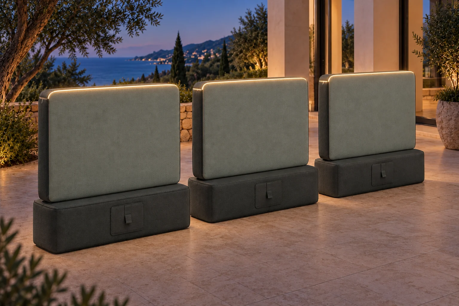 Design study
The product images show three example modules. Layout and module quantity change the schematic plan below. Dimensions and connections have not yet received structural approval.
YOUR LAYOUT FROM ABOVE
In a row · 3 Modules · 2 Connection points · 0 Corner adapters · 2 Free connection edges
ZipAround is intended to join matching connection edges into a row.
Schematic layout view. No dimensions, load capacity or approved parts list. Free connection edges have dedicated end closures. The product image above remains unchanged.
ZIPAROUND / STRUCTURAL CONNECTION
ZipAround is intended to structurally couple modules along their designated connection edges and transfer forces between components. The continuous connection is part of the construction concept; its design and load capacity will be tested on the complete system.
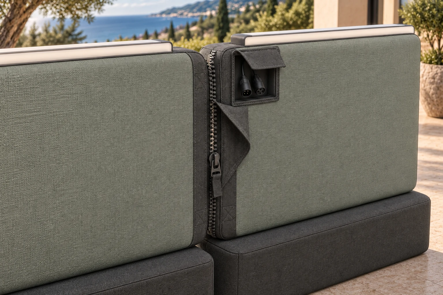
The connection zone, edge reinforcement, chain, slider, stops and attachments will be developed together as a structural joint. The matching counterpart and connection side should be clearly identifiable.
Care and cover replacement have a dedicated service opening. Air and water cells have separate envelopes and seals. Replacement follows an unloading and disassembly sequence that is still to be defined.
The light lines are intended to align visually. Separate electrical plugs, protected cable routes and strain relief are planned. Cables stay outside the ZipAround chain and carry no structural load.
A corner adapter connects two directions. Its connection sides will be developed for this purpose; a straight connection will not simply be bent around a corner.
Free connection edges have dedicated end closures. Protective flaps, slider positions and electrical ends should remain accessible and be protected against unintended opening.
Connection zones, corner adapters, end closures, covers and light carriers should be identified in the parts passport by position, connection side, dimensions and revision. Compatibility and replacement approval will be confirmed for each version.
Rows, corners and separate modules each require their own evidence. A connected assembly is not automatically more stable. Materials, connection geometry, permitted forces and operating limits are still to be defined.
Plan your layout conceptTHREE FUNCTIONS. CLEAR ACCESS.
The water base is intended to ballast the module. The panel and structural ZipAround joint form the proposed assembly. Lighting supports visual orientation. Each function has its own service access.
01 / WATER BASE
Separate inner water chambers with their own filling and draining access. The textile cover remains a replaceable surface and does not provide the water seal.
02 / PANEL & COUPLING
AirShell combines an air panel with a separate water base. HydroBase uses a framed panel. The ZipAround joint, corner adapters and end closures will be developed for each module. Compatibility between the two design approaches or with furniture and garden rooms has not yet been confirmed.
03 / LED LIGHTING
The fine light contour sits in its own upper channel. The light carrier, coupling and cable routing are intended to remain accessible for maintenance and for washing the cover separately.
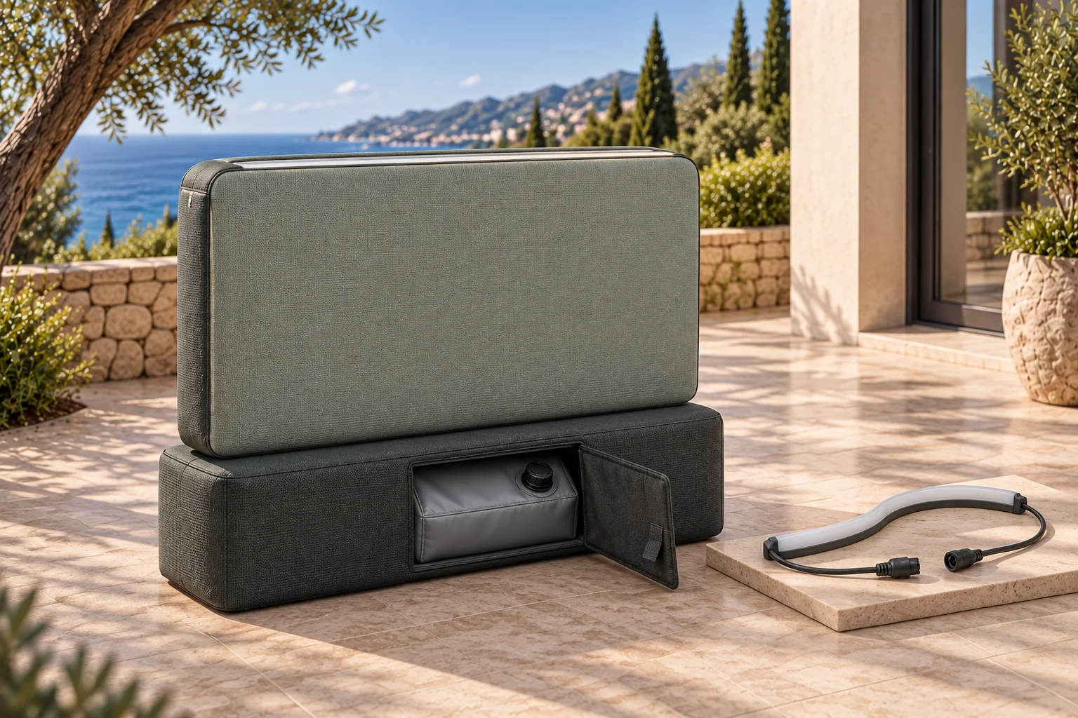
The filling and draining area is separate from the electrical service area. The LED carrier is intended to be removable in full. An accessible coupling and protected cable routes are part of the development.
The structural ZipAround connection between modules and the separate cover closure serve different purposes. Dedicated inner chambers seal the water and air; the electrical connector remains separate.
Explore the removable lighting conceptCARE / SEASONAL CHANGES / REPLACEMENT PARTS
Store LED carriers and connectors separately. Keep the entire electrical system out of the cover wash.
Empty inner chambers separately. Drainage, residual water and complete drying will be addressed for the specific design.
The textile cover is intended to be cleaned separately following care approval. Inner chambers, frame and electrical components remain separate.
Dry all parts completely. Pack flexible components and covers separately; rigid parts have their own storage space.
Water cells, valve components, covers, panels, ZipAround connection zones, matching counterparts, corner adapters, end closures, LED carriers and electrical connectors should be identified separately. The parts passport should preserve the position, connection side, dimensions and revision of the version actually delivered. Compatibility, permitted replacement and availability will be confirmed separately.
Explore the example parts mapTesting covers the complete ZipAround connection zone and its attachments, loading directions, peel stress, slider and stop retention, repeated opening, contamination and ageing. Tests then cover individual modules, rows, corners and ends at different fill levels, with water or air loss and under the intended loads. Ground conditions, wind, accessibility, pedestrian and escape routes, care and electrical components are part of the system assessment. A zip test alone does not establish the suitability of the space divider.
The current design direction is visual space division and visitor orientation. This concept is not approved for flood protection, vehicle restraint, fall protection or resistance to crowd pressure.
These sources provide assessment questions. They do not confirm product performance or conformity of our concept.